Design Patterns (4) UML Unified Modeling Language Complete Guide: Class Diagrams and Design Pattern Visual Expression
You can download the Design Pattern series source code from this design_pattern repo.
UML (Unified Modeling Language)
UML is the abbreviation for Unified Modeling Language, a standardized visual modeling language. It provides a universal way for developers to describe the structure and behavior of software systems using graphics.
In software development processes, UML plays an important role as a communication bridge. Whether it’s discussions between team members or requirement confirmations with clients, UML diagrams can clearly express complex software concepts.
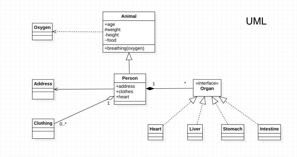
Don’t rush to write code, especially when encountering complex functionality. First think about how to design the architecture and draw UML diagrams, so the program will have readability, maintainability, and extensibility.
Next, we will introduce the most important elements and relationships in UML class diagrams one by one. These concepts will become fundamental tools for understanding design patterns.
Class
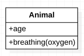
In UML class diagrams, a class is the most basic modeling element. Each class is represented using a rectangular box, with three sections from top to bottom:
- Class Name: The identifying name of the class, usually starting with a capital letter
- Attributes: Data members of the class, defining the object’s state
- Operations: Functions provided by the class, defining the object’s behavior
This three-layer structure provides complete class information, allowing developers to understand the class composition at a glance.
Interface
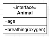
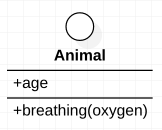
Interface defines method contracts that classes must implement, but does not contain actual implementation content. In UML, there are two common ways to represent interfaces:
Standard Representation
This representation looks similar to a class, both using rectangular boxes. The difference is that you need to add the <<interface>> marker above the class name, clearly indicating this is an interface rather than a regular class.
Lollipop Representation
This is a more concise representation method, using circular symbols to represent interfaces. This representation is particularly useful in complex class diagrams because it saves space and improves diagram readability.
Attribute
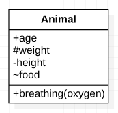
Attributes represent data members in a class, defining the state and characteristics of objects. In UML, attribute Visibility is an important concept that determines which code can access the attributes.
Visibility
UML uses specific symbols to indicate attribute visibility, with these symbols placed before the attribute name:
| Sign | Modifiers | Description |
|---|---|---|
+ | Public | Public access, accessible from anywhere |
# | Protected | Protected access, limited to class itself and subclasses |
~ | Package | Package access, accessible by classes within the same package |
- | Private | Private access, limited to class itself internally |
Proper use of visibility helps implement encapsulation principles, protecting object internal state from inappropriate access or modification.
Multiplicity
Multiplicity describes quantitative relationships between objects. When an association relationship exists between two classes, multiplicity markings can clearly express how many objects can participate in this association relationship on each end.
If not specifically marked, the default multiplicity is 1, indicating a one-to-one relationship.
| Sign | Amount | Real Application Example |
|---|---|---|
1 | 1 object | One person has one ID card |
* | Unlimited number | One school has many students |
n...m | At least n, at most m | One project team has 3-10 members |
Understanding multiplicity is very important for designing database relationships and inter-class relationships, helping developers correctly implement interaction logic between objects.
Dependency
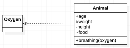
Dependency is the weakest form of association in UML, indicating that one class depends on another class to some extent to function properly. This relationship is usually temporary and does not establish persistent references in classes.
Characteristics of dependency relationships:
- Represents “A uses B” relationship
- Usually appears in method parameters, local variables, or return values
- Changes in dependent classes may affect user classes
- Arrow points from user to the depended-upon object
Graphical representation: Represented by dashed line + arrow

Real example: Animals use (depend on) oxygen during respiration to maintain survival. This is a temporary usage relationship.
Association
Association relationships are stronger than dependency relationships, indicating persistent structural connections between two classes. In association relationships, one object holds a reference to another object, usually existing as class attributes or global variables.
Characteristics of association relationships:
- Represents “A has a B” relationship
- Established at the class attribute level, is a persistent relationship
- Associated objects are relatively independent in lifecycle
- Includes two special forms: Aggregation and Composition
Graphical representation: Represented by solid line + arrow

Real example: Every person has (is associated with) an address. There’s a clear correspondence between person and address, but they can exist independently of each other.

Aggregation
Aggregation is a special form of association relationship, representing a “whole-part” relationship. In aggregation relationships, the whole owns the part, but the part can exist independently of the whole. This is a weaker ownership relationship.
Characteristics of aggregation relationships:
- Represents “A owns B” relationship
- Is a special form of Association, more semantic than general association
- Part objects can exist independently of whole objects
- When the whole disappears, parts can still exist
- Diamond symbol points to the owner (whole)
Graphical representation: Represented by solid line + hollow diamond

Real example: A person owns (aggregates) clothes. Even if this person no longer exists, the clothes can still exist and be used by others. This illustrates the independence of parts in aggregation relationships.

Composition
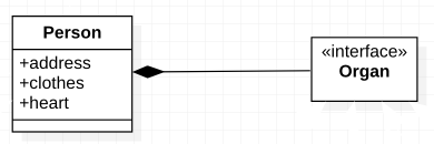
Composition is the strongest association relationship, also representing a “whole-part” relationship, but unlike aggregation, parts are completely dependent on the whole for existence. Once the whole disappears, parts will also disappear.
Characteristics of composition relationships:
- Represents “B is part of A” relationship
- Is the strongest ownership relationship
- Part objects cannot exist independently of whole objects
- When the whole disappears, parts also disappear
- Lifecycles are completely bound
- Diamond symbol points to the owner (whole)
Graphical representation: Represented by solid line + filled diamond

Real example: Humans have organs. When a person dies, organs also lose their meaning and function for existence. This complete lifecycle dependency is the characteristic of composition relationships.
(We won’t discuss organ transplantation to others here 😂)
Relationship Between Association, Aggregation, and Composition
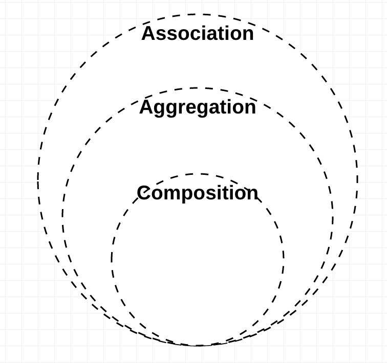
Understanding the differences between these three relationships is crucial for correctly modeling interactions between objects. They represent different degrees of coupling strength:
Increasing relationship strength:
- Association: Most basic structural relationship
- Aggregation: Special form of Association, representing weak ownership relationship
- Composition: Special form of Association, representing strong ownership relationship
Core difference lies in independence:
Aggregation means child objects can exist independently of parent objects.
For example: Class (parent) and Student (child). Even if the class is disbanded, students still exist.
Composition means child objects cannot exist independently of parent objects.
For example: House (parent) and Room (child). Without a house, rooms lose their meaning for existence.
This design consideration directly affects program memory management and object lifecycle design.
Realization / Implementation
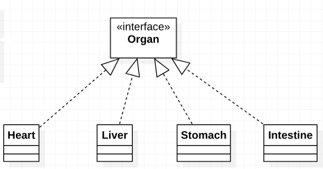
Realization relationships represent concrete class implementation of interface contracts. When a class implements an interface, it must provide concrete implementations of all methods defined in the interface.
Characteristics of realization relationships:
- Represents “B implements A” relationship
- Interface defines method signatures, implementing classes provide concrete logic
- Realizes the foundation of polymorphism, same interface can have multiple implementations
- Arrow points from implementing class to interface
- Supports the design principle of “depend on abstractions, not concretions”
Graphical representation: Represented by dashed line + hollow arrow

Real example: Heart, liver, stomach, intestines, etc., all must implement the “organ” interface. Each concrete organ has its own special functions but follows the basic organ contract.
Generalization / Inheritance
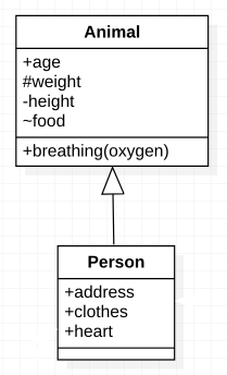
Inheritance relationships represent child classes inheriting attributes and methods from parent classes. This is one of the core concepts in object-oriented programming, realizing the foundation of code reuse and polymorphism.
Characteristics of inheritance relationships:
- Represents “C is-a A” relationship
- Child classes automatically have all public and protected members of parent classes
- Child classes can override parent class methods
- Child classes can add their own specific attributes and methods
- Arrow points from child class to parent class
- Supports polymorphism mechanism, parent class variables can reference child class objects
Graphical representation: Represented by solid line + hollow arrow

Real example: Humans are a type of animal. Humans inherit basic animal characteristics (like breathing, eating) while also having human-specific traits (like language, thinking ability).
Summary
UML class diagrams are indispensable communication tools in software design. Through this article’s introduction, we learned:
Basic Elements:
- Class: Three-layer rectangular box structure containing name, attributes, methods
- Interface: Abstract concept defining contracts, with two representation methods
- Visibility: Symbol system for controlling access permissions
Relationship Types and Strength:
- Dependency: Weakest relationship, temporary usage
- Association: Basic structural relationship, persistent connection
- Aggregation: Weak ownership relationship, parts can exist independently
- Composition: Strong ownership relationship, parts completely depend on whole
- Realization: Concrete implementation of interfaces
- Inheritance: is-a relationship, foundation of code reuse
Practical Application Value: Mastering these UML concepts will help you better understand the upcoming design pattern articles. Each design pattern will use UML diagrams to clearly show relationships and interaction methods between classes, making complex design concepts intuitive and easy to understand.
Are you ready? In the next article, we will enter the first concrete Design Pattern and begin exploring classic solutions in software design!
References
- 【UML】Class Diagram 類別圖 (上):Introduction 簡介
- 【UML】Class Diagram 類別圖 (下):Relationships 關係
- UML Relationships Types: Association, Dependency, Generalization
- What is the difference between association, aggregation and composition?
- UML Association vs Aggregation vs Composition
Note: If you have any suggestions, questions or different ideas, feel free to leave a comment or send me an email, we can discuss and grow together 🙂
Enjoy Reading This Article?
Here are some more articles you might like to read next: