Design Pattern 4: UML Diagrams - Visual Modeling Language for Software Architecture and Design Patterns
Download the complete Design Pattern series code from the design_pattern repo.
Introduction: The Power of Visual Software Design
UML (Unified Modeling Language) is a standardized visual language for planning and constructing software systems. It provides a common vocabulary for software developers to communicate design concepts effectively.
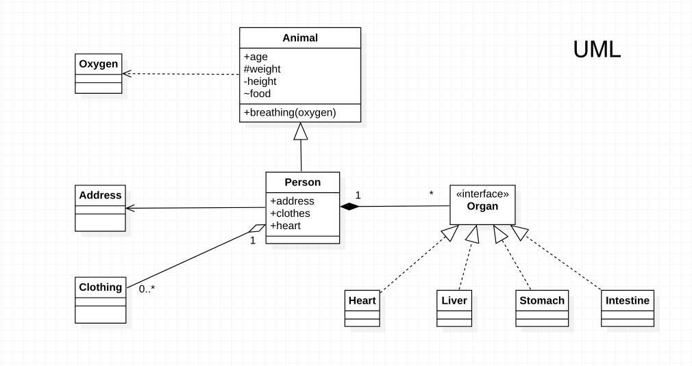
Best Practice: Don’t rush to write code, especially for complex functionality. First, think about how to design the architecture and draw UML diagrams. This ensures your code will be readable, maintainable, and extensible.
Real-World Applications
UML diagrams are essential for:
- Software Architecture: Planning system structure before implementation
- Design Patterns: Visualizing pattern relationships and interactions
- Team Communication: Sharing design ideas across development teams
- Documentation: Creating clear, visual documentation of systems
- Code Review: Understanding complex system interactions
Core UML Elements
Class Representation
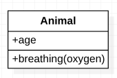
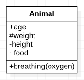
A class in UML is divided into three sections:
- Class Name
- Attributes (Properties)
- Operations (Methods)
Interface Representation
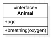
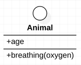
Interfaces can be represented in two ways:
Standard Notation
Similar to classes but with <<interface>> annotation above the class name.
Lollipop Notation
Uses a circle to represent the interface.
Visibility Modifiers
Visibility modifiers control access to class members:
| Symbol | Modifier | Description |
|---|---|---|
+ | Public | Accessible from anywhere |
# | Protected | Accessible within class and subclasses |
~ | Package | Accessible within the same package |
- | Private | Accessible only within the class |
Multiplicity in Relationships
Multiplicity defines the number of objects in a relationship:
| Symbol | Meaning | Description |
|---|---|---|
1 | Exactly one | Default relationship |
* | Zero or many | Unlimited number |
0..1 | Zero or one | Optional relationship |
1..* | One or many | At least one required |
n..m | Range | Between n and m objects |
UML Relationships
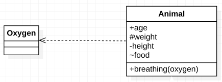
1. Dependency Relationship
- Purpose: Shows that one object depends on another
- Usage: Method parameters, return values, local variables
- Notation:
A uses a B - Visual: Dotted line with arrow pointing to the dependent object

Example: Animals depend on oxygen to breathe and survive.
2. Association Relationship
- Purpose: Shows that one object owns another object
- Usage: Class attributes, global variables
- Notation:
A has a C - Visual: Solid line with arrow pointing to the associated object

Example: Each person has (associates with) one address.

3. Aggregation Relationship
- Purpose: Shows ownership where objects can exist independently
- Notation:
A owns a B - Visual: Solid line with hollow diamond pointing to the aggregated object
- Characteristics: Weak relationship, objects can exist independently

Example: A person owns (aggregates) clothes. Both person and clothes can exist independently.

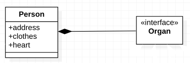
4. Composition Relationship
- Purpose: Shows ownership where objects cannot exist independently
- Notation:
C is a part of A - Visual: Solid line with filled diamond pointing to the composed object
- Characteristics: Strong relationship, composed object cannot exist independently

Example: Humans have organs. When a person dies, the organs become non-functional and cease to exist.
Note: We’re not considering organ transplantation scenarios here 😂
Relationship Hierarchy
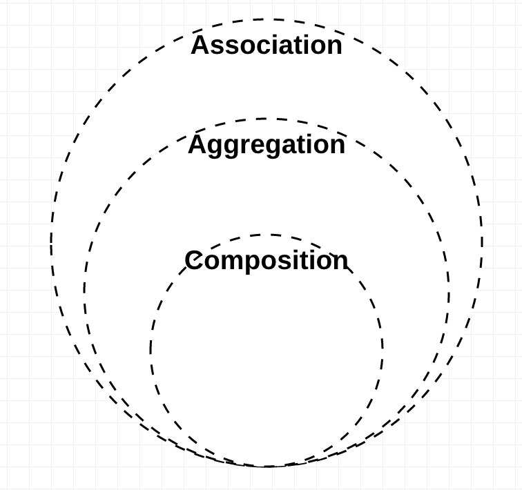
Aggregation and Composition are subsets of association, meaning they are specific cases of association. In both aggregation and composition, an object of one class “owns” an object of another class. But there is a subtle difference:
- Aggregation implies a relationship where the child can exist independently of the parent. Example: Class (parent) and Student (child). Delete the Class and the Students still exist.
- Composition implies a relationship where the child cannot exist independent of the parent. Example: House (parent) and Room (child). Rooms don’t exist separate from a House.
Implementation Relationships
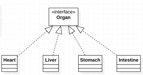
Realization/Implementation
- Purpose: Shows that one object implements another object
- Notation:
B implements A - Visual: Dotted line with hollow arrow pointing to the interface

Example: Heart, liver, stomach, and intestines implement the Organ interface.
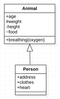
Generalization/Inheritance
- Purpose: Shows that one object inherits from another object
- Notation:
C is-a A - Visual: Solid line with hollow arrow pointing to the parent class

Example: A person is a type of animal.
Practical UML Examples
1. Simple Class Diagram
class User {
    private var id: String
    private var name: String
    private var email: String

    fun createPost(content: String): Post
    fun updateProfile(newName: String)
    fun deleteAccount()
}

class Post {
    private var id: String
    private var content: String
    private var author: User

    fun edit(newContent: String)
    fun delete()
}
UML Representation:
- User has a composition relationship with Post (posts belong to users)
- Post has a dependency on User (author parameter)
2. Design Pattern Example: Factory Method
interface Product {
    fun operation(): String
}

class ConcreteProductA : Product {
    override fun operation(): String = "ConcreteProductA"
}

class ConcreteProductB : Product {
    override fun operation(): String = "ConcreteProductB"
}

abstract class Creator {
    abstract fun createProduct(): Product

    fun someOperation(): String {
        val product = createProduct()
        return product.operation()
    }
}

class ConcreteCreatorA : Creator() {
    override fun createProduct(): Product = ConcreteProductA()
}

class ConcreteCreatorB : Creator() {
    override fun createProduct(): Product = ConcreteProductB()
}
UML Relationships:
- Creator has generalization relationship with ConcreteCreatorA and ConcreteCreatorB
- Creator has dependency on Product interface
- ConcreteProductA and ConcreteProductB implement Product interface
Best Practices for UML Modeling
1. Keep Diagrams Simple
- Focus on the most important relationships
- Avoid cluttering with unnecessary details
- Use multiple diagrams for different perspectives
2. Use Consistent Naming
- Follow naming conventions consistently
- Use clear, descriptive names for classes and relationships
- Include multiplicity when relationships are not 1:1
3. Show Only Relevant Information
- Include only attributes and methods relevant to the current context
- Use stereotypes (
<<interface>>,<<abstract>>) appropriately - Consider the audience when choosing detail level
4. Validate Relationships
- Ensure relationships accurately reflect the code
- Verify multiplicity constraints
- Check that inheritance hierarchies make sense
Common UML Tools
| Tool | Platform | Features | Best For |
|---|---|---|---|
| Lucidchart | Web-based | Collaboration, templates | Team projects |
| Draw.io | Web-based | Free, integration | Quick diagrams |
| Visual Paradigm | Desktop | Advanced features | Enterprise projects |
| StarUML | Desktop | Open source | Individual developers |
| PlantUML | Text-based | Version control friendly | Code-first approach |
Performance Considerations
| Diagram Type | Complexity | Readability | Maintenance |
|---|---|---|---|
| Simple Class | Low | High | Easy |
| Complex Class | High | Medium | Difficult |
| Package | Medium | High | Medium |
| Component | High | Medium | Difficult |
Anti-Patterns to Avoid
1. Over-Engineering
// Avoid: Too many relationships
class A
class B
class C
class D
// ... 20 more classes with complex relationships
2. Inconsistent Notation
// Avoid: Mixing different UML styles
class User {
    +name: String  // Public
    -id: String    // Private
    #email: String // Protected
    ~password: String // Package - inconsistent!
}
3. Missing Relationships
// Avoid: Not showing important dependencies
class UserService {
    fun createUser(user: User) {
        val validator = UserValidator() // Hidden dependency
        val repository = UserRepository() // Hidden dependency
    }
}
Related Design Patterns
- Factory Method: Uses inheritance and dependency relationships
- Strategy: Uses composition and interface realization
- Observer: Uses association and dependency relationships
- Decorator: Uses inheritance and composition
Conclusion
UML is an essential tool for software design and communication. Understanding UML diagrams will significantly help in software design, especially when working with design patterns. Key benefits include:
- Clear Communication: Visual representation of complex concepts
- Better Planning: Identify design issues before implementation
- Documentation: Create lasting documentation of system architecture
- Team Collaboration: Share design ideas effectively
The subsequent Design Pattern series articles will extensively use UML diagrams. Understanding these diagrams and arrow meanings is very helpful in software design.
Related Articles
- Design Pattern 1: Object-Oriented Concepts
- Design Pattern 2: Object-Oriented Design Principles
- Design Pattern 5: Simple Factory Pattern
- Design Pattern 6: Factory Method Pattern
Note: 如果有任何建議、問題或不同想法,歡迎留言或寄信給我,可以一起討論進步成長 🙂
Enjoy Reading This Article?
Here are some more articles you might like to read next: