3D Graphics Development Fundamentals Tutorial: Complete Analysis of Triangle Meshes, UV Mapping, and Vertex Indices
Introduction
When first encountering 3D graphics development, one is often confused by various professional terms and complex concepts. I faced the same challenges when developing AR features on iOS and Android recently.
Through in-depth learning and implementation, I gradually understood the core principles of 3D graphics. This article will introduce several of the most important fundamental concepts in an easy-to-understand way. Whether you’re just starting with 3D development or want to consolidate your foundational knowledge, these concepts will help you build a correct 3D thinking framework.
All Objects in the 3D World Are Composed of “Triangles”
You might wonder how computers render complex 3D objects. The answer is actually quite simple: decompose all curved surfaces into numerous tiny triangles. It’s like using countless small puzzle pieces to compose a complete picture.

In 3D modeling, these triangles that compose objects are called “Mesh.” The density of the mesh determines the model’s fineness: higher resolution means more and smaller triangles, resulting in smoother object surfaces. Conversely, lower resolution models have obvious edges but render faster.
This triangular decomposition method has an important advantage: triangles are the most stable geometric shapes, and any three points can determine a plane. Therefore, computer graphics processors can efficiently calculate the position, color, and lighting effects of each triangle.
What is UV Mapping?
Now that we understand that 3D objects are composed of triangles, the next problem to solve is: how do we make these monotonous triangles look like real objects? The answer is “UV Mapping.”
The process of projecting 2D images onto 3D model surfaces to give models textures
Imagine wrapping a gift box. First, you would unfold the box into a flat surface, then apply wrapping paper to the flat surface, and finally fold the box back to its original shape. UV Mapping works exactly the same way: “unfold” the surface of a 3D object into a 2D plane, then correctly map textures to each position.

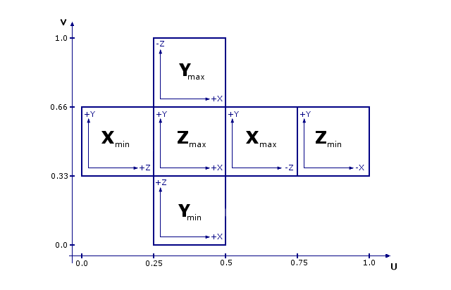
Taking a cube as an example, we can unfold the six faces into a cross-shaped 2D pattern. Then place the desired textures at corresponding positions, and the computer knows which part of the image to apply to which face of the cube. When the cube rotates in 3D space, the textures move correctly along with it, creating realistic visual effects.
In technical implementation, the UV coordinate system uses (U, V) to represent positions. U represents the horizontal axis (similar to X-axis), V represents the vertical axis (similar to Y-axis). The coordinate range is from (0,0) to (1,1), where (0,0) is usually at the top-left corner and (1,1) is at the bottom-right corner. This standardized coordinate system allows developers to precisely control texture position and scaling.

Vertices & Indices
Now we know that 3D objects are composed of triangles, and we understand how to apply materials to triangles. The next question is: how does the computer actually store and describe the shape and position of these triangles?
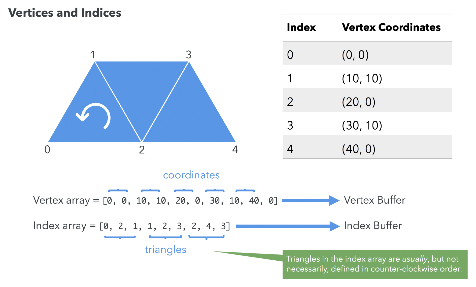
The answer is through the combination of “vertices” and “indices.” This method is more efficient and flexible than directly storing triangle coordinates. Let’s use a simple analogy to understand: imagine you want to draw a house using points and lines. You would first mark important points (door corners, window corners, roof vertices), then specify which points to connect to form lines.
In 3D graphics, we need two types of data:
- Vertices: Record the coordinates of each important position in 3D space, like landmark points on a map
- Indices: Define which vertices to connect to form triangles, like route maps connecting landmarks

Here’s a concrete example: suppose we have three vertices numbered 0, 1, 2. The index sequence [0, 2, 1] means connecting from vertex 0 to vertex 2, then to vertex 1, and finally back to vertex 0 to form a triangle.
There’s an important convention here: we usually use “counter-clockwise direction” to define the front face of triangles. This convention helps computers determine which side is the object’s exterior surface and which side is the interior, thus deciding which faces need rendering and which can be hidden to improve performance.
Supplement: Using the “Right-Hand Rule” to Determine Face Orientation
We mentioned earlier that we use counter-clockwise direction to define the front face, but how do we actually determine the orientation of a triangle? Here we can use the “right-hand rule” from physics (also called the right-hand screw rule).
The specific operation method is simple: rotate your right palm in the direction of the vertex index order (like turning a screw), and the direction your thumb points is the normal vector direction of that triangle face, which is the “outward” direction of this face.
This concept is very practical in actual development. For example, when you want to create a double-sided material object (like paper or fabric), you need to define two sets of indices to display both front and back faces simultaneously:
Front face: [0, 2, 1]  ← Counter-clockwise direction
Back face:  [0, 1, 2]  ← Clockwise direction (relative to front face)
By changing the connection order of vertices, we’re actually creating two triangles facing opposite directions. This way, no matter from which angle you view it, you can see the object’s surface rather than a transparent back face.
💡 Using this double-sided rendering technique is a common practice in AR applications and 3D games for handling thin objects (like leaves, fabric, paper).
Summary
Through this article, we explored three core concepts of 3D graphics development. First, we learned that all 3D objects are composed of triangle meshes, which is the fundamental principle of computer graphics. Next, we learned how UV Mapping precisely projects 2D textures onto 3D surfaces. Finally, we mastered how the vertex and index system efficiently describes and stores 3D geometric data.
Although these concepts may seem abstract, they are the foundation of all 3D technologies. Whether you’re developing iOS ARKit applications, Android ARCore projects, or web-based 3D games, this knowledge will help you better understand underlying principles and write more efficient code.
When you encounter 3D rendering problems in actual projects, returning to these basic concepts often provides clues to solutions. Remember, complex 3D scenes are all composed of these simple elements.
TIP
If you have different viewpoints, technical experiences, or want to discuss further 3D architecture design, feel free to leave comments or send me an email. Let’s exchange ideas and grow together 🙂
Enjoy Reading This Article?
Here are some more articles you might like to read next: